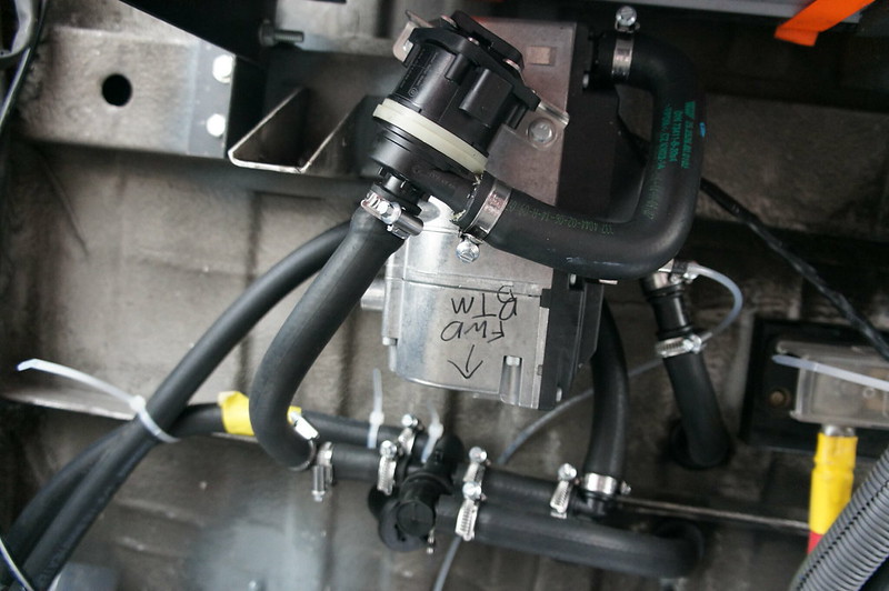
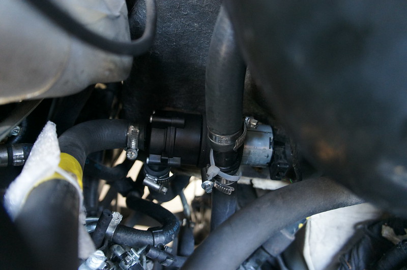
All the coolant lines for the Hydronic/Isotemp loop are completed. I am using this heater bypass valve. It is vacuum actuated so I can use the engine vacuum supply to control it. In the normal position both loops are isolated. When actuated the valve connects the espar D5/isotemp loop to the engine. This allows the engine to heat the water tank, or the espar D5 to heat the engine.
http://amzn.to/1OeATnf
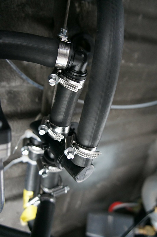
Here are the hose clamps I used.
http://amzn.to/1OeAYr3
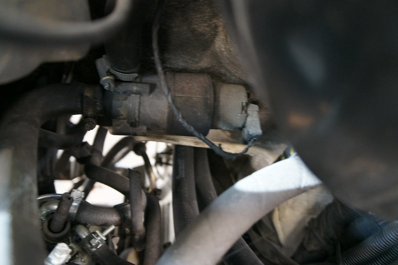
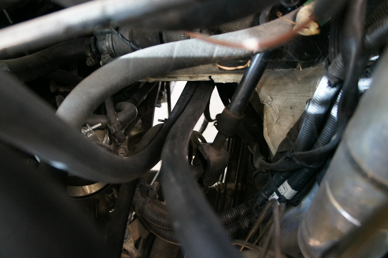
My stock cooling pump had almost completely worn out brushes, so I had a replacement on hand. Here is the original pump in its stock location below the brake booster.
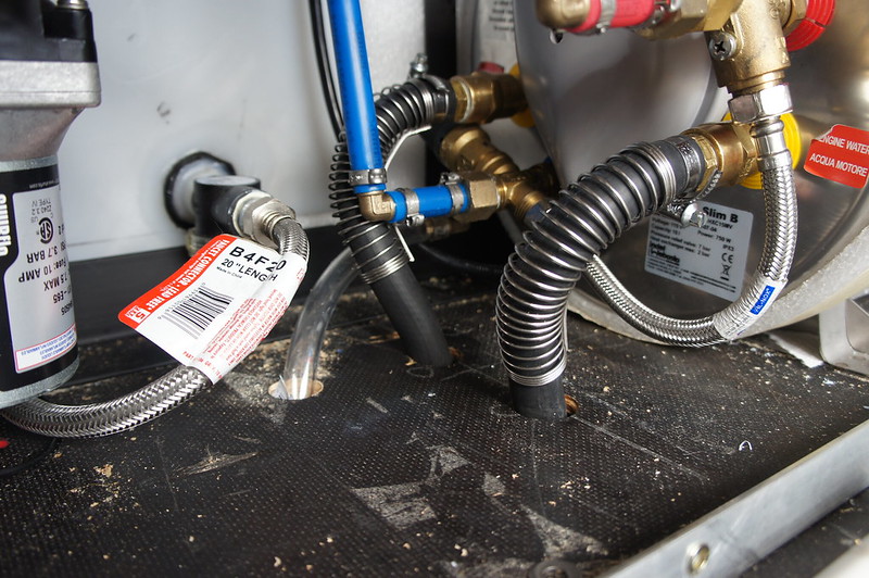
Here you can see the two hoses I ran for the espar loop.
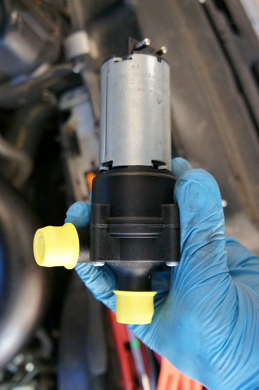
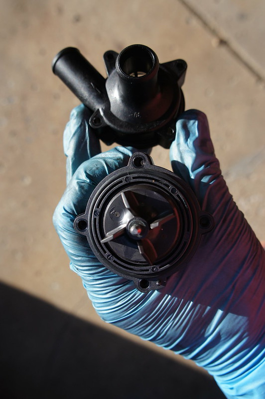
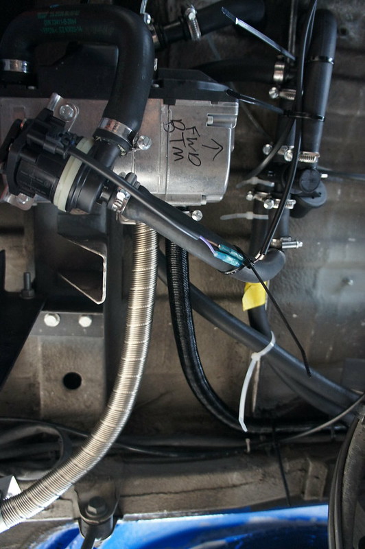
Here is the new bosch replacement. It uses an O-ring seal on the main case. This allowed me to split the pump body and re-clock it 180 degrees.
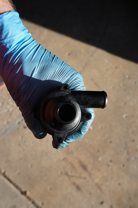
Here is the pump installed. I used a ¾”-5/8” coupler. The pump output now goes downward and into the espar/isotemp loop. The return from this loop continues upward and to the sprinter heater control valve. I will likely need to insulate the long hose runs to prevent reduction in cab heater output.
I took the van for a drive and no leaks that I could identify appeared. There were a few seeps on 2 connections at the heater bypass valve. I may need to change clamps if the seeps persist.
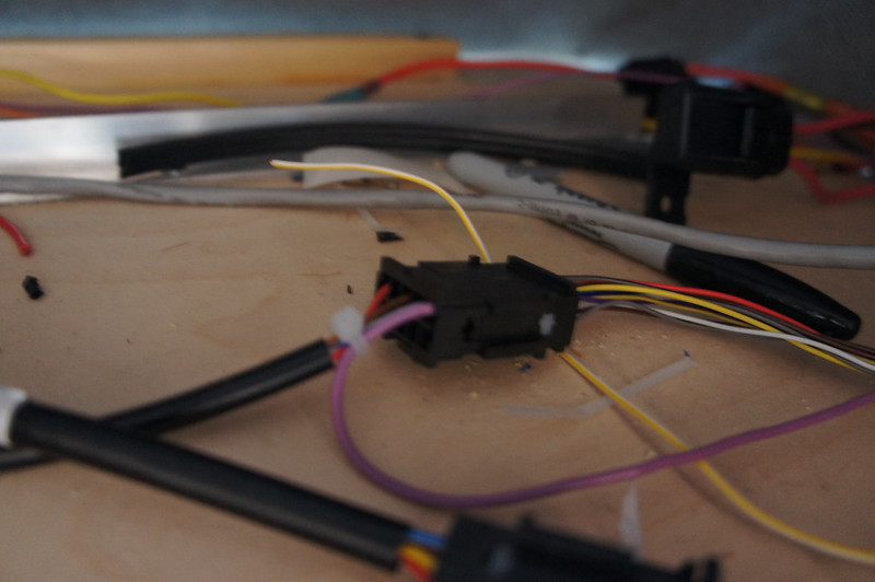
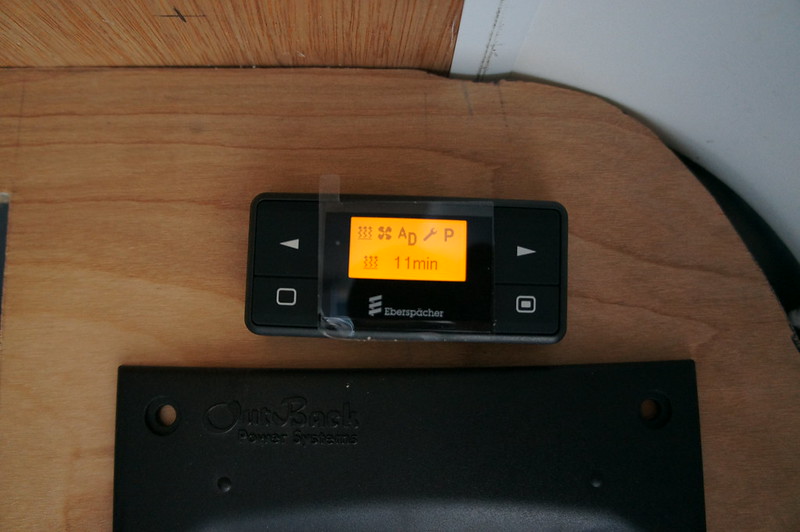
Wiring was very simple as just one wire needs connected to the EasyStart Controller, and 2 wires to the fuse panel for power. Control is via the EasyStart controllers Add-On feature. This allows the operation of a second heater of any type. Because It is connected using the diagnostic line the EasyStart can also read fault codes.

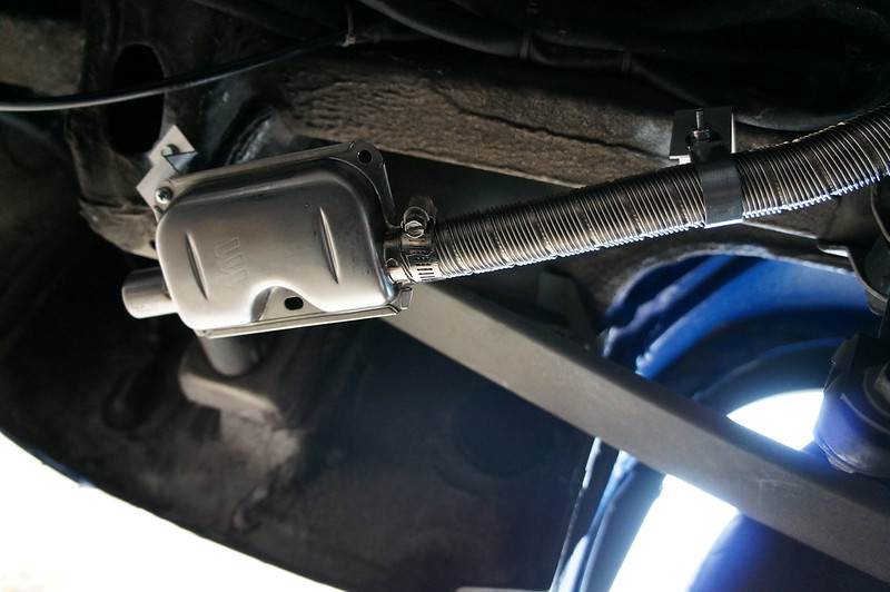
Here is the exhaust and intake routing. I am short a clamp, so the exhaust ending will have to wait for a bit.
No comments:
Post a Comment